
Course Description:
This course covers the electrical machines-three-phase
induction motor and generator, single phase ac motors, synchronous generator
and synchronous motor. It deals with the constructional details, operating
principle, characteristics, testing methods of the above machines.
Course content:
Unit 1. Three Phase Induction
Motor (15)
1.1 Constructional details – Yoke,
stator, stator windings, and rotor – squirrel cage type and phase wound type.
1.2 Operation – Production of
rotating magnetic field, operating principle, reversing the direction of
rotation.
1.3 Stand still condition –
equivalent circuit, starting current and starting torque.
1.4 Running condition - equivalent
circuit, running current and torque.
1.5 Torque-Speed characteristics,
effect of applied voltage on T-S characteristic, effect of rotor resistance on
T-S characteristic.
1.6 Power stages, losses and
efficiency
1.7 Starting methods – Direct
On-line starting, Primary resistor method, Autotransformer method, Star-Delta
method.
1.8 Speed control – Primary
voltage control method, Rotor resistance control method, frequency control
method, Cascade connection method.
1.9 Induction generator –
principle of operation, excitation requirement, voltage build-up process,
isolated and grid connected modes of operation.
Unit 2. Single Phase AC Motors
: (8 )
2.1 Split-phase induction
motor – Construction, concept of pulsating field produced by single phase
winding, double revolving field theory, Torque-speed characteristic,
self-starting by split-phase winding, Characteristics and
applications.
2.2 Capacitor start and
induction run motor – Operating principle, Characteristics and applications.
2.3 Capacitor start and run
motor- Operating principle, Characteristics and
applications
2.4 Shaded pole motor –
Operating principle, Characteristics and applications
2.5 AC series motor –
Operating principle, Characteristics and applications
Unit 3. Three-phase Synchronous
Generator (12)
3.1 Constructional details
and types.
3.2 Operation – Operating
principle, emf equation, armature winding parameters and its effect on emf
generation, relationship between speed, frequency and number of magnetic poles
in rotor, concept of geometrical degree and electrical degree.
3.3 Advantages of
stationary armature winding and rotating field winding.
3.4 Loaded operation –
effect of armature winding resistance, leakage reactance, armature reaction,
concept of synchronous impedance, equivalent circuit and phasor diagrams for
resistive, inductive and capacitive load, voltage regulation.
3.5 Synchronizing action
and synchronizing power Synchronous generator connected to infinite bus, effect
of excitation.
3.6 Parallel operation and
synchronization.
3.7 Related numerical
problems.
Unit 4. Synchronous Motor (10)
4.1 Principle of operation and
starting method.
4.2 General features and
applications
4.3 No-load and load operation
4.4 Effect of excitation on
armature current and power factor- V and inverted V curves.
4.5 Power-Angle characteristic.
Unit 1. Three Phase Induction Motor (15)


Introduction
• The
three-phase induction motors are the most widely used electric motors in
industry.
• They
run at essentially constant speed from no-load to full-load.
• However,
the speed is frequency dependent and consequently these motors are not easily
adapted to speed control.
• We
usually prefer d.c. motors when large speed variations are required.
• Like
any electric motor, a 3-phase induction motor has a stator and a rotor.
• The
stator carries a 3-phase winding (called stator winding) while the rotor
carries a short-circuited winding (called rotor winding).
• Only the stator winding is fed from 3-phase
supply.
• The
rotor winding derives its voltage and power from the externally energized
stator winding through electromagnetic induction and hence the name.
• The
induction motor may be considered to be a transformer with a rotating secondary
and it can, therefore, be described as a “transformer type” a.c. machine in
which electrical energy is converted into mechanical energy.
Advantages
(i) It has simple and rugged
construction.
(ii) It is relatively cheap.
(iii) It requires little
maintenance.
(iv) It has high efficiency and
reasonably good power factor.
(v) It has self starting torque.
Disadvantages
(i) It is essentially a constant
speed motor and its speed cannot be changed easily.
(ii) Its starting torque is
inferior to d.c. shunt motor.
Induction Machine
Construction
• A
3-phase induction motor has two main parts
(i) stator and (ii)
rotor.
• The
rotor is separated from the stator by a small air-gap which ranges from 0.4 mm
to 4 mm, depending on the power of the
motor.
1. Stator
• It
consists of a steel frame which encloses a hollow, cylindrical core made up of
thin laminations of silicon steel to reduce hysteresis and eddy current losses.
• A number of evenly spaced slots are provided
on the inner periphery of the laminations
• The
3-phase stator winding is wound for a definite number of poles as per
requirement of speed.
• Greater
the number of poles, lesser is the speed of the motor and vice-versa.
• When 3-phase supply is given to the stator winding,
a rotating magnetic field of constant
magnitude is produced.
• This
rotating field induces currents in the rotor by electromagnetic induction.
 |
| Fig: Stator |
2. Rotor
The rotor, mounted on a shaft, is a hollow laminated core having slots on its
outer periphery. The winding placed in these slots (called rotor winding) may
be one of the following two types:
(i) Squirrel cage type (ii) Wound type
(i)
Squirrel cage rotor
• It
consists of a laminated cylindrical core having parallel slots on its outer
periphery.
• One
copper or aluminum bar is placed in each slot.
• All
these bars are joined at each end by metal rings called end rings [See Fig.
(8.2)].
• This
forms a permanently short-circuited winding which is indestructible.
• The
entire construction (bars and end rings) resembles a squirrel cage and hence
the name.
- The rotor is not connected electrically to the supply but has current induced in it by transformer action from the stator

Fig: Squirrel Cage Rotor
(ii) Wound rotor
• It consists of a laminated cylindrical core
and carries a 3- phase winding, similar to the one on the stator.
• The
rotor winding is uniformly distributed in the slots and is usually
star-connected.
• The
open ends of the rotor winding are brought out and joined to three insulated
slip rings mounted on the rotor shaft with one brush resting on each slip ring.
• The
three brushes are connected to a 3-phase star-connected rheostat.
• At
starting, the external resistances are included in the rotor circuit to give a
large starting torque.
• These resistances are gradually reduced to
zero as the motor runs up to speed.

1.2 Operation
Production of Rotating Magnetic Field Due
to 3-Phase Currents
When a
3-phase winding is energized from a 3-phase supply, a rotating magnetic field
is produced. This field is such that its poles do no remain in a fixed position
on the stator but go on shifting their positions around the stator. For this reason,
it is called a rotating field. It can be shown that magnitude of this rotating
field is constant and is equal to 1.5 fm where fm is the maximum flux due to
any phase.


Here Øm is the maximum flux due to any
phase. Fig. shows the phasor diagram of the three fluxes. We shall now prove
that this 3-phase supply produces a rotating field of constant magnitude equal
to 1.5 Øm.

 |
| Fig 8.6 (i) At
instant 1 [See Fig. (8.6 (ii)) and Fig. (8.6 (iii))], the current in phase X is
zero and currents in phases Y and Z are equal and opposite. The currents are
flowing outward in the top conductors and inward in the bottom conductors. This
establishes a resultant flux towards right. The magnitude of the resultant flux
is constant and is equal to 1.5 Øm as proved under: At instant
1, wt = 0°. Therefore, the three fluxes are given by;  |

The phasor
sum of - Øy and Øz is the resultant flux Ør [See Fig. (8.7)]. It is clear that:
Ør=√(
Øy²+
Øz²+2*
Øy*
Øz*cosΘ)=1.5Øm
(ii) At instant 2, the current is maximum (negative)
in Øy phase Y and 0.5 maximum (positive)
in phases X and Y. The magnitude of resultant flux is 1.5 Øm proved under:
At instant
2, wt = 30°. Therefore, the three fluxes are given by;

The phasor
sum of Øx, - Øy and Øz is the resultant flux Ør.
iii) At
instant 3, current in phase Z is zero and the currents in phases X and Y are
equal and opposite (currents in phases X and Y arc 0.866 ´ max. value). The
magnitude of resultant flux is 1.5 Øm as proved under:
At instant
3, wt = 60°. Therefore, the three fluxes are given by;

The phasor
sum of Øx, - Øy and Øz is the resultant flux Ør.
iv) At
instant 4, the current in phase X is maximum (positive) and the currents in
phases V and Z are equal and negative (currents in phases V and Z are 0.5 ´ max.
value). This establishes a resultant flux downward as shown under:
At instant
4, wt =
90°. Therefore, the
three fluxes are given by;

The phasor
sum of Øx, - Øy and - Øz is the resultant flux Ør.
It follows from the
above discussion that a 3-phase supply produces a rotating field of constant
value (= 1.5 Øm, where Øm is the maximum flux due to any
phase).
Speed of rotating magnetic field
The speed at which the rotating
magnetic field revolves is called the synchronous
speed (Ns).

where f is the frequency of the supply and P is the number of poles per phase.
Principle of Operation
Consider a portion of 3-phase
induction motor as shown in Fig. (8.13). The operation of the motor can be
explained as under:
(i) When
3-phase stator winding is energized from a 3-phase supply, a rotating magnetic
field is set up which rotates round the stator at synchronous speed Ns (= 120 f/P).
(ii) The
rotating field passes through the air gap and cuts the rotor conductors, which
as yet, are stationary. Due to the relative speed between the rotating flux and
the stationary rotor, e.m.f.s are induced in the rotor conductors. Since the
rotor circuit is short-circuited, currents start flowing in the rotor
conductors.
(iiii) The
current-carrying rotor conductors are placed in the magnetic field produced by
the stator. Consequently, mechanical force acts on the rotor conductors. The
sum of the mechanical forces on all the rotor conductors produces a torque
which tends to move the rotor in the same direction as the rotating field.
(iv) The
fact that rotor is urged to follow the stator field (i.e., rotor moves in the
direction of stator field) can be explained by Lenz’s law. According to this
law, the direction of rotor currents will be such that they tend to oppose the
cause producing them. Now, the cause producing the rotor currents is the
relative speed between the rotating field and the stationary rotor conductors.
Hence to reduce this relative speed, the rotor starts running in the same
direction as that of stator field and tries to catch it.

Click here to watch How Induction motor works?
Direction of rotating magnetic field
The phase sequence of the three-phase voltage applied to the
stator winding in Fig. (8.6 (ii)) is X-Y-Z. If this sequence is changed to
X-Z-Y, it is observed that direction of rotation of the field is reversed i.e.,
the field rotates counterclockwise rather than clockwise. However, the number
of poles and the speed at which the magnetic field rotates remain unchanged.
Thus it is necessary only to change the phase sequence in order to change the
direction of rotation of the magnetic field. For a three-phase supply, this can
be done by interchanging any two of the three lines. As we shall see, the rotor
in a 3-phase induction motor runs in the same direction as the rotating
magnetic field. Therefore, the direction of rotation of a 3-phase induction
motor can be reversed by interchanging any two of the three motor supply lines.

Slip
The difference between the
synchronous speed Ns
of
the rotating stator field and the actual rotor speed N is called slip. It is
usually expressed as a percentage of synchronous speed i.e.,

(i)
The
quantity Ns
- N
is sometimes called slip speed.
(ii)
When
the rotor is stationary (i.e., N = 0), slip, s = 1 or 100 %.
(iii)
In
an induction motor, the change in slip from no-load to full-load is hardly 0.1%
to 3% so that it is essentially a constant-speed motor.
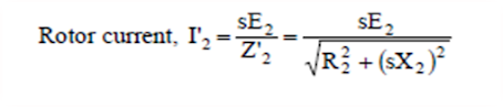
Rotor Current
Frequency
The frequency of a voltage or current induced due to the relative speed between a vending and a magnetic field is given by the general formula;
Frequency = NP/120
P = Number of poles
For a rotor speed N, the relative speed between the rotating flux and the rotor is Ns - N. Consequently, the rotor current frequency f' is given by;

i.e., Rotor current frequency = Fractional slip x
Supply frequency
At
any slip s,
Rotor e.m.f./phase
= sE2
Rotor
reactance/phase = sX2
Rotor frequency =
sf
where E2,X2 and
f are the corresponding values at standstill
Rotor Current
At standstill. Fig. (8.15 (i)) shows one phase of the rotor circuit at standstill.

When running at slip s. Fig. (8.15 (ii)) shows one phase of the rotor circuit when the motor is running at slip s.

Rotor Torque
The torque T developed by the rotor
is directly proportional to:
(i) rotor current
(ii) rotor e.m.f.
(iii) power factor of the rotor circuit
\ T µE2I2 cosf2 or, T = KE2 I2 cosf2
where I2 = rotor current at standstill
E2 = rotor e.m.f. at standstill
cos f2 = rotor p.f. at standstill
Note.
The values of rotor e.m.f., rotor current and rotor power factor are taken for
the given conditions.
Analysis at Standstill Condition
Standstill
condition is the instant of starting. At this instant, the speed of the rotor
is zero. Therefore the relative speed Ns-N is maximum, slip is maximum(s=1) and
maximum emf will induce in the rotor circuit(just like in secondary winding in
a transformer) and the frequency of emf induced in rotor circuit is same as
that of supply voltage frequency ‘f’ and is given by :
f=
(Ns*P)/120
The
equivalent circuit of the induction motor at standstill condition is very
similar to the equivalent circuit of a transformer. The stator winding is
analogous to the primary winding of the transformer and rotor circuit is
analogous to the secondary winding of the transformer. The per phase equivalent
circuit of a three phase induction motor is as shown in fig8.11.

Let E2 =
rotor e.m.f. per phase at standstill
X2 = rotor
reactance per phase at standstill
R2 = rotor
resistance per phase

Analysis of Running Condition
The equivalent circuit of
the induction motor at running condition can be written as:

Let the
rotor at standstill have per phase induced e.m.f. E2, reactance X2 and resistance
R2. Then under running conditions at slip s,

Running Torque, Tr µ E'2 I'2 cosf'2

Torque-Slip Characteristics
If a curve
is drawn between the torque and slip for a particular value of rotor resistance
R2, the graph thus obtained is called torque-slip characteristic. The general
equation of torque is given by:


Thus for maximum
torque (Tm)
under running conditions :
Rotor resistance/phase =
Fractional slip ´ Standstill
rotor reactance/phase
Hence
maximum torque will develop at a speed corresponding to slip s=R2/X2. If the
motor is overloaded so that speed goes below this value, the motor will not be
able to develop more torque to overcome the increased load.

Effect of Change of Supply
Voltage

Therefore, the starting torque is very sensitive to changes
in the value of supply voltage. For example, a drop of 10% in supply voltage
will decrease the starting torque by about 20%. This could mean the motor
failing to start if it cannot produce a torque greater than the load torque
plus friction torque.
Effect of rotor
resistance on T-S characteristics
At normal
running condition, Tr µ s/R2
At starting, Ts µ R2/s
Therefore, if we add some resistance in series with rotor winding (that
we can do in case of slip-ring rotor), the starting torque will increase, but
running torque will decrease. Fig below show the effect of rotor resistance on
the T-S characteristics of induction motor.

Here two
curves are shown- one for rotor resistance of R2 and other for rotor
resistance of 2R2. At a particular speed N1, the running
torque is equal to OT1 when rotor resistance is R2. At
the same speed, the running torque is only OT2 when the rotor resistance is 2R2.
The starting torque of the motor is equal to OC with rotor resistance R2
and the motor gives higher starting torque with rotor resistance 2R2.
Hence, external rotor resistance are used where high starting torque is
required. Once the motor has picked up to its normal operating speed (N), the
external rotor resistance is removed to improve the running torque.
Example 9.11
A 4-pole, 3-phase, 50Hz induction
motor has a star connected rotor. The rotor has a resistance of 0.1 ohm per
phase and standstill reactance of 2 ohm per phase. The induced emf between the
slip rings is 100V. If the full load speed is 1460 rpm, calculate
i.
The slip
ii.
The emf induced in the rotor in each
phase
iii.
The rotor reactance per phase
iv.
The rotor current and
v.
Rotor power factor.
Assume slip rings are short
circuited.
Example: 9.1
A 6-pole, 3 phase induction motor is
connected to 50 Hz supply. If it is running at 970 rpm, find the slip. (ans=3%)
Example 9.2
A 3-phase induction motor is wound
for 4 poles and is supplied from 50 Hz system. Calculate: i) the synchronous
speed ii)the speed of the motor when slip is 4% and iii) the rotor current
frequency when the motor runs at 600 rpm.(ans: 1500rpm, 1440rpm, 30Hz)
Example 9.3
A 50 Hz 4-pole 3-phase induction
motor has a rotor current of frequency of 2 Hz. Determine i)the slip and ii)
speed of the motor. (4%, 1440rpm)
Example 9.4
A 500 hp, 3-phase, 440 V, 50 Hz induction
motor has a speed of 950 rpm on full load. The machine has 6-poles. Calculate
the full load slip and rotor frequency. (5%, 2.5 Hz)
Tutorials
1.
A 2-pole, 3-phase,50-Hz induction
motor is running on no load with a slip of 4%. Calculate i) synchronous speed
ii) speed of the motor (ans: 3000rpm, 2880rpm)
2. The frequency of emf in the stator of a 4-pole,3-phase induction motor is 50Hz and that in the rotor is 1.5 Hz. Determine i) the slip ii) speed of the motor (ans: 3%, 1455 rpm)
3. A 3-phase, 50Hz induction motor has 8 poles. If the full-load slip is 2.5 %, determine i) synchronous speed ii) rotor speed iii) rotor frequency (ans: 750rpm, 731 rpm, 1.25Hz)
1.6 Power
stages, losses and efficiency
The input
electric power fed to the stator of the motor is converted into mechanical
power at the shaft of the motor. The various losses during the energy
conversion are:
1. Fixed
losses
(i) Stator
iron loss
(ii)
Friction and windage loss
The rotor
iron loss is negligible because the frequency of rotor currents under normal
running condition is small.
2.
Variable losses
(i) Stator
copper loss
(ii) Rotor
copper loss
Fig. (8.20) shows how electric power fed to the stator of an induction motor suffers losses and finally converted into mechanical power.

The
following points may be noted from the above diagram:
(i)
Stator input, Pi = Stator output + Stator losses
=
Stator output + Stator Iron loss + Stator Cu loss
(ii)
Rotor input, Pr = Stator output
It is because stator output is entirely transferred to the rotor through air gap by electromagnetic induction.
(iii)
Mechanical
power available, Pm = Pr - Rotor Cu loss
This mechanical power available is the gross rotor output and will produce a gross torque Tg.
(iv)
Mechanical
power at shaft, Pout = Pm - Friction and
windage loss
Mechanical power available at the
shaft produces a shaft torque Tsh.
Clearly, Pm - Pout = Friction and
windage loss

Induction Motor
Torque

Rotor Output
If Tg
newton-metre is the gross torque developed and N r.p.m. is the speed of the rotor,
then,
Gross rotor
output = 2pNTg/60 watts
If there
were no copper losses in the rotor, the output would equal rotor input and the
rotor would run at synchronous speed Ns.

Starting of 3-Phase Induction Motors
The induction motor is
fundamentally a transformer in which the stator is the primary and the rotor is
short-circuited secondary. At starting, the voltage induced in the induction
motor rotor is maximum (Q s
= 1). Since the rotor impedance is low, the rotor current is excessively large.
This large rotor current is reflected in the stator because of transformer
action. This results in high starting current (4 to 10 times the full-load current)
in the stator at low power factor and consequently the value of starting torque
is low.
Methods of Starting 3-Phase Induction
Motors
The method to be employed in
starting a given induction motor depends upon the size of the motor and the
type of the motor. The common methods used to start induction motors are:
(i)
Direct-on-line starting
(ii)
Stator resistance starting
(iii)
Autotransformer
starting
(iv)
Star-delta starting
(v)
Rotor resistance
starting
Methods (i) to (iv) are
applicable to both squirrel-cage and slip ring motors. However, method (v) is
applicable only to slip ring motors. In practice, any one of the first four
methods is used for starting squirrel cage motors, depending upon ,the size of
the motor. But slip ring motors are invariably started by rotor resistance
starting.
(i) Direct-on-line starting
This method of starting in just what the name implies—the
motor is started by connecting it directly to 3-phase supply. The impedance of
the motor at standstill is relatively low and when it is directly connected to
the supply system, the starting current will be high (4 to 10 times the
full-load current) and at a low power factor. Consequently, this method of
starting is suitable for relatively small (up to 7.5 kW) machines.
(ii) Stator resistance starting
In this method, external resistances are connected in series
with each phase of stator winding during starting. This causes voltage drop
across the resistances so that voltage available across motor terminals is
reduced and hence the starting current. The starting resistances are gradually
cut out in steps (two or more steps) from the stator circuit as the motor picks
up speed. When the motor attains rated speed, the resistances are completely
cut out and full line voltage is applied to the rotor.
This method suffers from two drawbacks. First, the reduced
voltage applied to the motor during the starting period lowers the starting
torque and hence increases the accelerating time. Secondly, a lot of power is
wasted in the starting resistances.

(iii) Autotransformer starting
This method also aims at connecting the induction motor to a
reduced supply at starting and then connecting it to the full voltage as the
motor picks up sufficient speed. Fig. (8.31) shows the circuit arrangement for
autotransformer starting. The tapping on the autotransformer is so set that
when it is in the circuit, 65% to 80% of line voltage is applied to the motor.
At the instant of starting, the change-over switch is thrown
to “start” position. This puts the autotransformer in the circuit and thus
reduced voltage is applied to the circuit. Consequently, starting current is
limited to safe value. When the motor attains about 80% of normal speed, the
changeover switch is thrown to “run” position. This takes out the
autotransformer from the circuit and puts the motor to full line voltage.
Autotransformer starting has several advantages viz low power loss, low
starting current and less radiated heat. For large machines (over 25 H.P.),
this method of starting is often used. This method can be used for both star
and delta connected motors.

(iv) Star-delta starting
The stator winding of the motor is designed for delta
operation and is connected in star during the starting period. When the machine
is up to speed, the connections are changed to delta. The circuit arrangement
for star-delta starting is shown in Fig. (8.33). The six leads of the stator
windings are connected to the changeover switch as shown. At the instant of
starting, the changeover switch is thrown to “Start” position which connects
the stator windings in star. Therefore, each stator phase gets V 3 volts where
V is the line voltage. This reduces the starting current.
When the motor picks up speed, the changeover switch is
thrown to “Run” position which connects the stator windings in delta. Now each
stator phase gets full line voltage V. The disadvantages of this method are:
(a) With star-connection during starting, stator phase
voltage is 1 3 times the line voltage. Consequently, starting torque is ( )2 1
3 or 1/3 times the value it would have with D-connection. This is rather a
large reduction in starting torque.
(b) The reduction in voltage is fixed.
This method of starting is used for medium-size machines
(upto about 25 H.P.).

(v)
Starting of Slip-Ring Motors
Slip-ring motors are invariably started by rotor resistance starting. In this method, a variable star-connected rheostat is connected in the rotor circuit through slip rings and full voltage is applied to the stator winding as shown in Fig. (8.34).

(i)
At starting, the handle of rheostat is set in the OFF
position so that maximum resistance is placed in each phase of the rotor
circuit. This reduces the starting current and at the same time starting torque
is increased.
(ii)
As the motor picks up
speed, the handle of rheostat is gradually moved in clockwise direction and cuts
out the external resistance in each phase of the rotor circuit. When the motor
attains normal speed, the change-over switch is in the ON position and the
whole external resistance is cut out from the rotor circuit.
Speed Control of Induction Motor
The slip of
an induction motor is very small (<3%) so that it is essentially a constant
speed motor. Therefore, it is suitable for use in essentially constant speed
drive systems. However, many industrial applications require several speeds or
a continuously adjustable range of speeds. Traditionally, dc motors have been
used in such adjustable speed applications. However, dc motors are expensive
and require frequent maintenance of commutators and brushes. On the other hand,
the induction motors (squirrel cage motors) are cheap, rugged, have no
commutators and are suitable for high speed applications. The engineers have
devised several methods to change the speed of induction motors.
The relation
between motor speed (N), synchronous speed (Ns) and slip(s) is given by:
N= (1-s) Ns
N=
(1-s)*(120f/P)
This
equation reveals that the speed of an induction motor can be changed by the
following methods:
1. By changing the number of stator
poles(P)
2. By changing the line frequency(f)
3. By changing the slip (s) for a given
load. The slip can be changed by:
a) By changing the applied voltage
b) By changing resistance in the rotor
circuit
c) By inserting foreign voltage of
appropriate frequency in the rotor circuit
1. By changing the number of stator poles(P)
The synchronous speed of rotating magnetic field is inversely
proportional to the number of magnetic poles in stator winding. Stator winding
can be designed in such a way that they can be connected as 2-pole or 4-pole or
6-pole with the help of special switch and accordingly we can operate the motor
at three different speeds, but smooth change in speed is not possible with this
method.
2. By changing the line frequency(f)
From the formula of the synchronous speed of the induction motor, we know
that by changing the line frequency f, the synchronous speed Ns of the motor
and hence the running speed N can be changed. A major difficulty with this
method is that it involves the use of 3-phase variable frequency power supply.
3. By changing the applied voltage
We know that the torque developed (T) by an induction motor is directly proportional to the square of applied voltage (V) i.e TaV2. Therefore, by changing the applied voltage, the torque and hence speed (or slip) of the motor can be changed. Fig 10.21 shows the arrangement to control the speed of induction motor by changing the applied voltage.


Limitation: The stator voltage control method is
the cheapest and the easiest method of speed control of induction motors.
However, it is rarely used because of the following drawbacks:
a) A large change in voltage is required
for a relatively small change in speed.
b) The large change in voltage results in large change in the flux density. This affects the magnetic conditions and hence performance of the motor.
1. By changing rotor circuit resistance
This method of speed control is suitable only for slip ring motors. The
speed of the motor can be decreased by adding external resistance to the rotor
as shown in fig. Under normal running condition, the relation between torque
(T) and slip (s) of an induction motor is given by:
T a (s/R2)
R2 is the rotor resistance per phase. It is clear from the above equation that for a given torque, s a R2. Therefore slip can be increased by increasing the rotor resistance

Cascade Connection Method
In this method of speed control, two motors having different number of
poles are mounted on a common shaft as shown in figure 8.16. The stator winding
of the motor A is supplied by main supply voltage of frequency ‘f’. The second
motor B is supplied by the voltage induced in the rotor of the first motor A through
slip rings. Therefore the frequency of voltage applied to the stator of the
second motor will be different from the main supply frequency. Now the two
motors will try to run with two different speed corresponding to two different
frequencies. As the both motors are couple to a common shaft, the system will
run at a new speed.

Induction Generator
If an induction motor whose stator
windings are connected to a 3-phase line is driven by a prime-mover at a speed
higher than synchronous speed, it acts as a generator. It converts the
mechanical energy it receives from the prime-mover into electrical energy and
this electrical energy is supplied to the mains. Such a machine is called an
induction generator or asynchronous generator. When speed of the generator
exceeds the synchronous speed, the slip(s) becomes negative.

As soon as the engine speed exceeds
the synchronous speed, the motor becomes a generator, delivering active power P
to the electrical systems to which it is connected. However, to create its
magnetic field, the motor has to absorb reactive power Q. this power can come
only from the lines. Consequently, the reactive power Q flows in the opposite
direction to the active power P as shown in fig.
We have seen that an induction generator will deliver power only if it is supplied with proper reactive power to create its magnetic field. For this reason, an induction generator is generally connected to a 3-phase line. However, reactive power may be supplied by a group of capacitors connected to the terminals of the motor as shown in fig. in that case, the induction generator does not require external source for supply of reactive power.

Voltage
Build up process in Induction Generator
An induction machine with capacitors connected across its terminals, when driven by a prime mover, builds up the voltage in a manner similar to that of a de shunt generator. The voltage build-up process in a dc machine depends upon the residual magnetism in the field poles and the final steady terminal voltage is determined by the resistance of the field circuit. In case of the induction generator, the residual magnetism in the magnetic circuit of the machine is sufficient to generate a small ac voltage in the stator. This small ac voltage causes the capacitor to draw a leading current or a lagging magnetizing current through the magnetizing reactance.
When a proper value of capacitor is
selected, the magnetizing current can be made sufficient to increase the
existing air gap flux. With an increased air gap flux, induced voltage
increases resulting in more magnetizing current to flow. This process of
voltage build-up continues until induce voltage reaches a limit constrained by
the saturation curve of the machine and the reactance of the capacitor. The
steady state value of the emf generated corresponds to the point of
intersection between magnetization curve and volt-amp characteristic of the
capacitor.
 |
| Fig: Equivalent circuit for no load excitation circuit |
iµ= Magnetizing current
Xm
= Magnetizing reactance
e = emf
induced in stator
Self-excitation occurs when Xc ≤ (Xm + X)

Curve ‘a’ shown in fig 11 is the magnetization characteristics of the machine and the lines C1, C2, C3 and C4 represents the volt-amp characteristics of different rating capacitors used for excitation.
For any point on the excitation curve, e/iµ
= (Xm+X)
= XC
If the induction generator is operated to supply only isolated local load without connecting the inter-connected power system bus, then such operation is known as isolated mode of operation. It is clear from the T-S characteristic shown in Fig.12 that the induction generator operates at different slip (speed) at different loading condition. At full load it operates at slip 's1', whereas at no-load it operates at slip 's2'. Hence, if the water flow into the turbine is not regulated to match the varying load condition, the frequency of generated voltage varies from full load to no-load.

However, if the water flow into the turbine is not regulated (i.e. constant discharge and head is maintained) and electronic load controller is used, the speed and frequency call be made constant at the varying load conditions. The electronic load controller keeps the total load on the generator constant as shown in Fig.13.

When the consumer's load decreases or increases by some
amount, the electronic control circuit will increase or decrease the power
consumed by ballast load by same amount so that the total power consumption (PL
+ PB) remains constant and equal to power generated by the generator
(PG) resulting in constant speed operation at varying consumer's
load conditions.
Induction generator is more robust and cheaper than
synchronous generator. But an induction generator cannot generate reactive
power demanded by the load. Whereas, synchronous generator can generate
reactive power demanded by the load with the help of dc excitation system
provided in the rotor winding. Induction generator is becoming more popular in
Micro Hydro Power (MHP) plant in rural area, where the consumer's loads are
mostly resistive (lighting and heating).
Induction generator in grid connected mode of operation:
If the induction generator is connected to the bus of large inter-connected grid system as shown in Fig.14, then such operation is known as grid connected mode of operation. In such operation, no Electronic load controller is required. At varying mechanical power input from the turbine, the induction generator injects varying amount of power to the grid and frequency of voltage of induction generator will be automatically constant and equal to grid voltage and frequency. The voltage and frequency of grid always remains constant, because it has frequency governors and voltage controllers in the power stations of the grid. In this mode of operation, even the excitation capacitor is not required. The grid supplies reactive power required for induction generator to maintain air-gap flux.

Synchronizing to grid:
The synchronizing
process of Induction Generator to grid is very simple with compare to that for
Synchronous generator. The IG is driven by turbine keeping the switch (S1) open
and speed is gradually increased by opening the turbine valve. When the speed
reaches little greater than the synchronous speed, then the switch (S1) shall
be closed as shown in Fig.15 , then the IG gets synchronized automatically and runs at constant speed which is little greater than the
synchronous corresponding to the slip.
Unit 2: Single Phase Motors
Single-phase motors are the most familiar of all electric motors because they are extensively used in home appliances, shops, offices etc. It is true that single phase motors are less efficient substitute for 3-phase motors but 3-phase power is normally not available except in large commercial and industrial establishments. Even where 3-phase mains are present, the single-phase supply may be obtained by using one of the three lines and the neutral.
Types of Single-Phase Motors
Single-phase motors are generally built in the fractional-horsepower range and may be classified into the following four basic types:
1. Single-phase induction motors
(i) split-phase type (ii) capacitor type (iii) shaded-pole type
2. A.C. series motor or universal motor
3. Repulsion motors
(i) Repulsion-start induction-run motor
(ii) Repulsion-induction motor
4. Synchronous motors
(i) Reluctance motor (ii) Hysteresis motor
Single-Phase Induction Motors
Construction and Concept of pulsating field produced by single phase winding
A single phase induction motor is very similar to a 3-phase squirrel cage induction motor. It has (i) a squirrel-cage rotor identical to a 3-phase motor and (ii) a single-phase winding on the stator.

Unlike a 3-phase
induction motor, a single-phase induction motor is not self-starting but
requires some starting means. The single-phase stator winding produces a
magnetic field that pulsates in strength in a sinusoidal manner. The field
polarity reverses after each half cycle but the field does not rotate.
Consequently, the
alternating flux cannot produce rotation in a stationary squirrel-cage rotor.
However, if the rotor of a single-phase motor is rotated in one direction by
some mechanical means, it will continue to run in the direction of rotation. As
a matter of fact, the rotor quickly accelerates until it reaches a speed
slightly below the synchronous speed. Once the motor is running at this speed, it
will continue to rotate even though single-phase current is flowing through the
stator winding. This method of starting is generally not convenient for large
motors. Nor can it be employed fur a motor located at some inaccessible spot.
This strange behavior of single-phase induction motor can be explained on the
basis of double-field revolving theory.
Double-Field Revolving Theory
This theory is based on the fact that an alternating sinusoidal flux (ɸ= ɸm cos wt) can be represented by two revolving fluxes, each equal to one-half of the maximum value of alternating flux (i.e., ɸm/2) and each rotating at synchronous speed (Ns = 120 f/P, w= 2*pi*f) in opposite directions. The above statement will now be proved. The instantaneous value of flux due to the stator current of a single-phase induction motor is given by;
ɸ=ɸm coswt


 |
| Fig 9.13 |
 |
| Fig 9.14 |
 |
| Fig 9.15 |
 |
| Fig 9.16 |
Operation
 |
| Fig 9.17 |
iii. The effect of the shading coil is to cause the field flux to shift across the pole face from the unshaded to the shaded portion. This shifting flux is like a rotating weak field moving in the direction from unshaded portion to the shaded portion of the pole.

 |
| Fig: Construction of alternator |
 |
| Fig: Salient pole rotor |
 |
| Fig: Cylindrical type rotor |

 |
| Fig 10.4 |


 |
| Fig. (10.14) |
 |
| Fig.(10.16) |
 |
| Fig.(10.17) |

 |
| Fig.(10.19) |

 |
| Fig.(10.45) |
 |
| Fig.(10.46) |
 |
| Fig.(10.50) |
 |
| Fig.(10.51) |


It should be noted that
the shorting strip, which short circuits the rotor bars, contains holes for
bolting to the next set of damper winding on the next pole. In this way, a
complete squirrel cage winding is formed. Although the bar's' are not of the
capacity to carry the rated synchronous motor load, they are sufficient to
start the motor as induction motor—Star-Delta or auto transformer' methods are
used to reduce the starting current drawn by the motor. It is practically
impossible to start a synchronous motor with its field excited. Even with
un-excited condition, the rapidly rotating magnetic field of the stator will
induce extremely high voltage in many turns of the field winding. Therefore.,
it is better to short circuit dc field winding during the starting period;
whatever voltage and current are induced in it may then aid in producing
induction motor action.
All the above methods shall be used with the synchronous motor without load. In order to start the synchronous motor with load, phase wound damper winding shall be used so that external resistance can be inserted to produce high starting torque. Fig.9.21 shows the schematic diagram of phase wound damper winding for starting synchronous motor.

Such
motor will have rotor with five slip ring. Two for the dc field excitation and
three for ac star connected wound damper winding The motor is started with full
external resistance per phase and dc field circuit open As the motor approaches
synchronous speed, the starting resistance is reduced and, when the field
voltage is applied, the motor pulls into synchronism.
Equivalent diagram

No-load and Loaded operation:
It had already been
explained that a synchronous motor is not self-starting. It had to be speeded
up to synchronous speed by some auxiliary means, the supply to the rotor
winding of the rotor had to be switched on, then the rotor poles will get
magnetically locked up with stator poles. However the engagement between the
stator and rotor poles is not absolutely rigid one. As the load on the motor
increases, the rotor progressively tends to fall back in phase (but net in
speed) by some angle, but the motor still continue to with the synchronous
speed.
At no-load, if there is no power loss in the motor, the stator poles and rotor poles will be along the same axis and phase difference between the applied voltage ‘V’ and the back emf (developed in the armature winding) will be exactly 1800 (See Fig9.22(a) ). But this not possible in practice because some power loss takes place due to iron loss and friction loss. Hence the rotor pole lags by some angle 'a' with the stator pole and the phasor diagram will be as shown in Fig.9.22(b) The current drawn by armature at no-load is given by
Ia = (V-Eb)/Zs = ER/Zs
ER = Net voltage across the armature
Zs = Synchronous impedance per phase

In case of dc motor, the
speed of the armature decreases with increase in load due to which the back emf
decrease and then the armature current will increase to overcome the increased
load. But in case of synchronous motor, the speed does not change with load
When the load on a synchronous motor increases, the rotor poles lags the stator
poles by larger angle ‘a’ and the phase between V and Eb will
increase (note that magnitude of Eb will remain constant) so that
the net voltage ER will increase and the armature current will increase.
Effect of Excitation
The dc current supply to
the rotor field winding is known as excitation in synchronous motor. As the
speed of synchronous motor is constant, the magnitude of back emf remains
constant provided the flux per pole produced by the rotor does not change. If
the magnitude of back emf can be changed by field excitation. If the excitation
is changed at a constant load, the magnitude of armature current and power
factor will change. By changing the excitation, the motor can be operated at
both lagging and leading power factor. This fact can be explained as follows:
The value of excitation for which the magnitude of back emf Eb is equal to applied voltage V is known as 100% excitation. If the excitation is more than 100%, then the motor is said to be over excited and if the excitation is less than 100%, then the motor is said to be under excited.

Consider a synchronous
motor operating with a constant load. Fig 9.23(a) shows the phasor diagram for
the case of 100% excitation i.e. when Eb= V (in magnitude). The armature
current Ia lags behind V by a small angle Ø. ϴ is
the phase angle between Ia and ER, whose magnitude is given by ϴ
= tan-1(Xs /Ra ). Since Xs and Ra are constant, angle ϴ also
remains constant.
If the motor is under
excited, the magnitude of Eb will be less than V. Therefore the resultant of Eb
and V (i.e. ER) will shift upward by some angle, then the direction
Ia will also shift by same angle so that angle ϴ
again remains constant as shown in fig.9.23 (b). Here the magnitude of Ia has
increased and Ia lags V by greater angle so that power factor is decreased, but
the active component Ia cos ϴ remains same so that
output power also remains constant.
Fig.9.23(c) represents
the condition for over excited motor (i.e. when Eb>V). Therefore the resultant
voltage vector ER is pulled in the anti-clockwise and Ia also is
shifted in anti-clockwise direction. It is seen that now motor is drawing a
leaking current. It may also happen for same value of excitation, that Ia may
be in phase with V. i.e. power factor is unity as shown in fig-.9.23(d). At
this instant the current drawn by motor is minimum.
The following two
important points shall be understand clearly from the above discussion."
i) The magnitude of armature current varies with excitation. The current has larger values at both low and high values of excitation. In between. it has minimum value corresponding to a certain excitation for which power factor is unity The variation of Ia with excitation are shown in fig.9.24 which are known as 'V' curves.

ii) For the same input,
armature current varies between a wide range and power factor also vary
accordingly with excitation. When over excited motor runs with leading power
factor and the motor runs with lagging power factor when under excited. The
variations power factor with excitation is also shown in Fig 9.24 and known as
inverted 'V' curve. It would be noted that minimum armature current
corresponding to unity power factor.
Power angle Characteristic of Cylindrical Rotor Machines:
Fig.9.25 (a) shows the circuit diagram and phasor diagram of a synchronous machine in generating mode and Fig.9.25 (a) shows the 'circuit diagram and phasor diagram of a synchronous machine in motoring mode. The machines are assumed to be connected to the infinite bus bar having a voltage of ‘Vt’ and resistance of the stator winding is neglected and only the reactance of the machine has been considered.


From the eqn (9.8) it is clear that the electrical power of the machine P, is proportional to Sind, where 5 is the phase angle between Vt and Eb. This angle 5 is known as power angle. The eqn (9-8) can be represented by a curve as shown in Fig.9.26.

Servo
motors
A servo system is one in which the output is some mechanical variable like position, velocity or accelerators. Such systems are automatic control systems in which output is some mechanical function such as controlling the position of the shaft, controlling angular speed of the shaft etc. As seen earlier, the motors used in such control systems are driven by the signal which is derived based on the error information supplied to the controller. These motors used in such servo systems or servomechanism are called as servomotors. These motors are low power rating motors and can drive the load directly, hence these motors are usually coupled to the load through a gear train for power matching purpose.
 |
| Figure 1 Servo mechanism |
The servomotors are basically classified depending upon the nature of the electric supply used for its operation. The electric supply can be a.c. or d.c. in nature hence basic classification is obviously a.c. servomotors and d.c servomotors.
Types
1.
AC
Servomotors
2.
DC
Servomotors
a.
Field
Controlled DC Servomotors
b.
Armature
Controlled DC Servomotors
c.
Permanent
Magnet Armature Controlled DC servomotors
Stepper
motor (stepping motors or step motors)
A
stepper motor is an electromagnetic motor that rotates by a specific number of
degrees in response to an input electrical signal. Typical step sizes are 2,
2.5, 7.5 and 15 degrees for each electrical pulse. It is to be noted that there
is no continuous energy conversion (electrical to mechanical) so that motor
does not rotate continuously as in a conventional electric motor.
Construction
of Permanent magnet stepper motor
It
consists of stator and rotor. Fig shows a two phase, two pole PM stepper motor.
The stator coils are grouped to form 2 phase winding i.e. phase A winding and
phase winding B winding. The phase winding terminals are brought out for dc
excitation.
 |
| Figure 2 Construction and operation of PM stepper motor |
Operation of PM stepper motor
For
this stepper motor, the number of rotor poles Nr=2 and number of phases m=2
Step
angle,a=360/(m*Nr)=90 degree/step
I.
When
only phase A winding is excited by a
contant curresnt as shown in fig I, stator tooth 1 becomes south pole. This makes
the north pole of the PM rotor to align (parallel) with the south pole (stator
tooth 1) of the stator. The rotor will remain locked in this position as long
as phrase A winding remains energized. Under this condition step angle a=0.
II.
If
phase A winding is de-energised and phase B winding is energersed as shown in
fig ii, stator tooth 2 becomes south pole. As a result, the north pole of the
PM rotor aligns with the south pole of the stator. Thus the rotor has displaced
90 degree in the anticlockwise direction.
III.
If
phase B is de-energised and phase A is excited with reverse current ( current
in it is opposite to the case I above) , the rotor will further rotate 90
degree in anticlockwise direction as shown in fig iii.
IV.
So
far the rotor has completed one half revolution. However, if we continue the
appropriate switching, the rotor will complete one revolution in 90 degree
steps.
We can change the step angle (a) of
a stepper motor by changing the number of rotor poles Nr and the number of
phases (m).

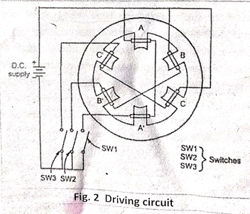
Driving
Circuit of Stepper motor
A
Stepper Motor Driver is a circuit or device that provides the necessary current
and voltage to a Stepper Motor so that it has a smooth operation. A Stepper
Motor is a type of DC Motor that rotates in steps. The main difference between
a simple DC Motor and a Stepper Motor is that through a Stepper Motor, we can
achieve precise positioning with the help of digital control. A Stepper Motor
rotates precisely by synchronizing the pulse signals from a controller, which
are given through a Driver. A Stepper Motor Driver is a circuit that takes the
pulse signals from a controller and converts them in to Stepper Motor Motion.
Two axis AC machine
It
is known that in case of non-salient pole type synchronous machine, the air gap
is uniform. Due to uniform air gap, the field flux as well as armature flux
vary sinusoidally in the air gap. In non-salient rotor machine, air gap length
is constant and reactance is also constant. Due to this the mmfs of armature
and field act upon the same magnetic circuit all the time hence can be added
vectorically. But in salient pole type machines the length of the air gap
varies and the reluctance also varies. Hence the armature flux and field flux
cannot vary sinusoidally in the air gap. The reluctances of the magnetic
circuits on which mmfs act are different in case of salient pole motors.
Hence
the armature and field mmfs cannot be treated in a simple way as they can be in
a non-salient pole machines. In two axis machine, the armature mmf can be
divided into two components.
1.
Components
acting along the pole axis called direct axis.
2.
Component
acting at right angles to the pole axis called quadrature axis.
The
component acting along direct axis can be magnetizing or demagnetizing. The component
acting along quadrature axis is cross magnetizing. These components produce the
effects of different kinds.
Let
Fi be the mmf wave produced by field winding, then it always acts along the
direct axis. This mmf is responsible to produce an excitation emf Ef which lags
Ff by an angle 90 degree.
When
armature carries current, it produces its own mmf wave FAR. This can
be resolved in two components, one acting along d-axis (cross-magnetising). Similarly,
armature current Ia also can be divided into two components, one along direct
axis and along quadrature axis.

Sir, there is an absence in the explanation of the second point of operation of split phase induction motors.
ReplyDelete